
Quick Answer
HVAC symbols are the shorthand mechanical drawings use for ducts, diffusers, grilles, dampers and equipment, defined in each set's own legend, and reading HVAC drawings means working through the legend, the scale, the duct runs, the tags and the schedules in that order. Each step tells you how to read the next one. Below are what a mechanical drawing set contains, the common HVAC symbols and abbreviations, how to read duct sizes and fittings, how to read air devices and dampers, how to match equipment tags to the schedules, two worked examples, a checklist and our view on what estimators get wrong.
What you'll find below:
- What is on each type of mechanical sheet, from M-001 to the schedules
- Common HVAC symbols, abbreviations and equipment tags
- How to read duct sizes, and why a run priced at one size is wrong
- How 12 VAV boxes on a plan hide 8 pipe connections in the schedule
- A sheet-by-sheet order for turning HVAC drawings into a takeoff
- A checklist before the mechanical takeoff goes to pricing
What Is in an HVAC Drawing Set?
An HVAC drawing set is the mechanical part of the construction drawings: a legend and notes sheet, floor plans showing ductwork and equipment, roof plans, sections, details, and schedules that describe every piece of equipment and air device. The plan shows where things go. The other sheets say what they are.
The United States National CAD Standard, published by the National Institute of Building Sciences, gives mechanical sheets the letter M in its Uniform Drawing System (version 6, 2014), with the next digit naming the sheet type. On a set that follows it, you'll find:
| Sheet | What it holds | What an estimator takes from it |
|---|---|---|
| M-0 series | Legend, abbreviations, general notes | What every symbol and note means on this job |
| M-1 series | Floor and roof plans | Duct runs, sizes, air devices, equipment locations |
| M-3 series | Sections | Duct elevations, clearances, what runs above the ceiling |
| M-4 series | Enlarged plans | Mechanical rooms, shafts, congested areas |
| M-5 series | Details | Equipment connections, supports, roof curbs, damper installs |
| M-6 series | Schedules and diagrams | Equipment, air devices, dampers, control diagrams |
Many sets also split ductwork and piping onto separate plans, sometimes with their own letter, and put plumbing on P sheets and fire protection on F sheets. Our guide on how to read construction blueprints covers the sheet index, title blocks and scales that apply to every discipline.
What Do Common HVAC Symbols and Abbreviations Mean?
Common HVAC symbols show supply, return and exhaust ductwork, air devices, dampers, equipment and controls, but each set defines its own in a legend on the first mechanical sheet, so read it before you open a plan. The same shape can mean different things on two jobs.
The HVAC symbols and labels you'll see on most mechanical plans:
| Symbol or label | What it shows | What to check |
|---|---|---|
| Duct drawn as two parallel lines with a size, such as 24x12 | Rectangular duct, width by depth | Which number is the side shown in plan, per the legend |
| Duct with a round size, such as 12" or 12Ø | Round duct | Material and whether it is spiral or flexible |
| Square with an X or diagonal lines, with a tag | Diffuser or grille | Supply or return, and the tag that points to the schedule |
| Rectangle with a line or arrow across the duct | Volume damper | Manual or motorized, and where access is needed |
| FD, SD or FSD next to a damper | Fire, smoke or combination fire and smoke damper | Rating and the access door each one needs |
| Wavy or dashed duct line | Flexible duct | Maximum length allowed in the specs |
| Arrows along a duct | Airflow direction | Supply, return or exhaust |
| A number with CFM next to an air device | Airflow in cubic feet per minute | Matches the schedule row for that device |
| Tag such as AHU-1, RTU-2, EF-3, VAV-2-4 | Air handling unit, rooftop unit, exhaust fan, VAV box | The row in the equipment schedule |
| T in a circle | Thermostat or temperature sensor | Who supplies and wires it |
Abbreviations vary as much as symbols. SA, RA, EA and OA (supply, return, exhaust and outside air), AFF (above finished floor), BOD (bottom of duct), NIC (not in contract) and TYP (typical) are common, but the legend has the final say. A smoke damper marked NIC is still an item someone has to install, so find out who.
Why Check the Scale and General Notes on Every Sheet?
Check the scale and general notes on every mechanical sheet before you measure, because duct lengths are taken from the plan and the notes set rules that change every run. Enlarged plans and details are drawn at different scales from the floor plan.
Read the scale under each view, then confirm it against the graphic scale bar or a known dimension, such as a column spacing. If a sheet has no scale you can trust, count the air devices and equipment on it and leave duct lengths until the designer confirms the scale.
The general notes carry rules like "all duct sizes are clear inside dimensions", "provide volume dampers at every branch takeoff" or "all exposed duct shall be painted". Notes like these add fittings, dampers and finish work across the whole job.
How Do You Read Ductwork on HVAC Drawings?
Read ductwork by tracing each system from the equipment out to the last air device, noting the size at every change and every fitting along the way, because a duct run is priced by its size, length, gauge and fittings, not just its length. Start at the unit and follow the air.
A duct run on a plan carries more than a line:
- Size labels at the start of the run and after every change. Rectangular duct is shown as width by depth, and round duct by diameter.
- Transitions and reducers wherever the size changes, usually after a branch.
- Fittings such as elbows, tees, wyes and offsets, each a separate item on the takeoff.
- Branch takeoffs to each air device, often with a volume damper.
- Insulation or lining, shown by a hatch, a note or the specs.
- Access doors at dampers, coils and fans.
Sheet metal is priced by weight, so the ductwork gauge for each size matters as much as its length. Our ductwork weight calculator turns duct sizes and lengths into pounds of sheet metal by gauge.
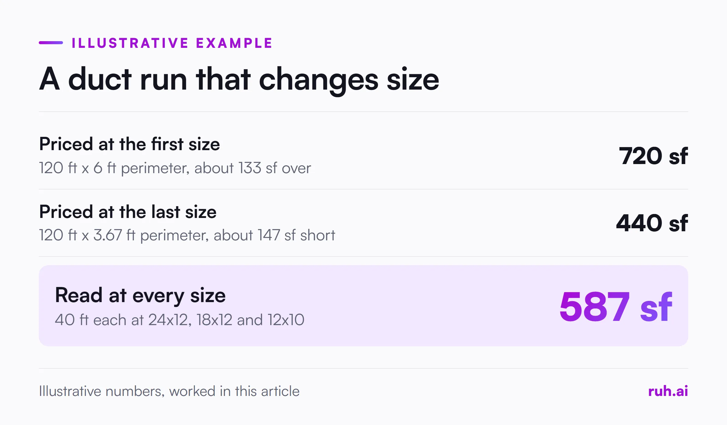
Worked example: a run that changes size. These numbers are illustrative. A 120 foot supply trunk is drawn as 40 feet of 24x12, then 40 feet of 18x12 after the first branch, then 40 feet of 12x10 after the second.
The perimeters are 6 feet, 5 feet and about 3.67 feet. The sheet metal surface is 40 x 6 + 40 x 5 + 40 x 3.67 = 240 + 200 + 146.7, or about 587 square feet. Priced at the first size for its whole length, the run is 120 x 6 = 720 square feet, about 133 square feet more than it needs. Priced at the last size, it is 120 x 3.67 = 440 square feet, about 147 square feet short.
How Do You Read Diffusers, Grilles, Registers and Dampers?
Read air devices by their tags: each diffuser, grille or register on the plan carries a tag and often an airflow in CFM, and the air device schedule says its type, size, neck size, finish and accessories. Count by tag, not by shape.
Supply diffusers deliver air, return grilles take it back, and exhaust grilles remove it from rooms like restrooms. Registers are grilles with a built-in damper. Two devices that look the same on the plan can have different sizes, patterns or finishes in the schedule, so a count by shape alone prices the wrong thing.
Dampers need the same care. Volume dampers balance airflow, fire and smoke dampers protect openings in rated walls and floors, and each fire or smoke damper needs access for inspection. Count them from the plan, match the type to the schedule, and check the rated walls on the architectural life safety plans, where dampers are required but not always drawn.
How Do You Read an HVAC Equipment Schedule?
Read an HVAC equipment schedule by matching every tag on the plans to its row, then reading each column for the size, capacity, electrical data, weight and accessories that the plan symbol doesn't show. The plan says where the unit is. The schedule says what you are buying and connecting.
A mechanical equipment schedule lists, for each tag:
| Column | What it tells you | Why it matters for the takeoff |
|---|---|---|
| Tag and description | AHU-1, RTU-2, EF-3, VAV-2-4 | Links the row to the plan |
| Capacity | Airflow, cooling and heating | Confirms the unit you are pricing |
| Electrical | Voltage, phase and load | Power connections, often by the electrical trade |
| Weight | Operating weight | Rigging, crane and structural supports |
| Accessories | Curbs, coils, filters, disconnects, controls | Items the plan symbol doesn't show |
| Remarks | Basis of design, "furnished by others" | What you install versus what you buy |
Worked example: VAV boxes and reheat coils. These numbers are illustrative. A floor plan shows 12 VAV boxes. The schedule shows 4 of them have hot water reheat coils. Each reheat box adds a supply and a return pipe connection and a control valve, so the schedule adds 4 x 2 = 8 pipe connections and 4 control valves that the plan symbol never shows.
Rooftop equipment works the same way. A rooftop unit tag on the roof plan points to a schedule row with its curb, weight and accessories, and the weight decides whether a crane is needed.
What Should You Cross-Check Before You Count?
Cross-check the plans against the sections, details and specifications before you count, because they hold the scope that a plan view can't show: heights, supports, insulation, testing and who furnishes what. Plans show the layout, not the full scope.
Sections show where duct runs above the ceiling, and whether it fits. Details show equipment connections, curbs, hangers and damper installations. The specifications set duct construction, gauge, sealing, insulation, testing and balancing, and they name what is furnished by others.
Check what the other trades' sheets say too. Electrical sheets show power to mechanical equipment, structural sheets show supports and roof openings, and architectural sheets show rated walls where fire dampers go. Our guide to drawing and spec conflicts covers what to do when two documents disagree.
From Drawings to Takeoff: A Sheet-by-Sheet Order
Take off HVAC drawings in a fixed order, so every item is counted once and nothing is skipped: equipment first, then ductwork, then air devices, then dampers and accessories. The order follows the air.
- Equipment. Count every tag from the plans and roof plan, and match each one to its schedule row.
- Ductwork. Trace each system from its unit, measuring length at each size and counting fittings.
- Air devices. Count diffusers, grilles and registers by tag, and match each tag to the schedule.
- Dampers and accessories. Volume, fire and smoke dampers, access doors and flexible connections.
- Insulation and lining. Measure from the duct takeoff, per the specs.
- Piping and connections. Hydronic and refrigerant connections to coils and units.
- Everything else. Supports, curbs, controls, testing and balancing, per the specs and details.
Our guide on how to bid HVAC as a subcontractor covers what comes after the takeoff: structuring the proposal and what the GC checks.
HVAC Drawing Checklist Before Pricing
Run this before the mechanical takeoff goes to pricing:
- The legend, abbreviations and general notes have been read on every mechanical sheet.
- The scale is confirmed on every view, and sheets with no trustworthy scale have counts only.
- Every duct run is measured at each size, with fittings counted separately.
- Gauge is set by size from the specs, not assumed.
- Every equipment tag on the plans has a schedule row, and every schedule row has a plan location.
- Air devices are counted by tag and matched to the air device schedule.
- Fire and smoke dampers are counted, with access doors, and checked against rated walls.
- Sections and details have been checked for scope above the ceiling, supports and connections.
- Items furnished by others, and items marked NIC, are clear in writing.
- Anything without a price is a labelled allowance, never a zero.
Common Mistakes When Reading HVAC Drawings
Most HVAC takeoff errors start before the count: a legend not read, a scale not checked, or a tag never matched to its schedule. These are the ones to watch for:
| Mistake | What it costs | How to avoid it |
|---|---|---|
| Measuring a run at one size | Too much or too little sheet metal | Read the size after every transition |
| Counting air devices by shape | Wrong sizes, patterns and finishes | Count by tag and use the schedule |
| Skipping the equipment schedule | Missed coils, curbs, disconnects and connections | Match every tag to its row |
| Ignoring the general notes | Dampers, painting or lining required everywhere | Read every M-0 sheet first |
| Missing fire dampers in rated walls | Dampers and access doors left out | Check the life safety plans |
| Taking duct heights from the plan | Runs above the ceiling and offsets missed | Follow the section callouts |
What Estimators Get Wrong About HVAC Drawings
Four positions on reading HVAC drawings, argued as our view, not as data.
Duct is not priced by the foot. Size, gauge and fittings decide the cost. A length without a size is half a quantity.
The schedule is the second half of the plan. A tag on the plan is a pointer, and the schedule row is where the money is.
Follow the air, not the sheet. Tracing each system from its unit to its last device catches the fittings and branches that a sheet-by-sheet scan misses.
Fire dampers live on the architectural sheets too. The rated walls decide where they go, and the mechanical plan doesn't always draw them all.
The Honest Assessment: What Still Falls Short
Mechanical drawings are among the most changed sheets in a set. Coordination between ductwork, piping, structure and ceilings continues after bid, and duct routes can move once the trades draw their coordination models.
Bid sets also leave some decisions to the installer, such as fitting choices and exact routing. And the split of controls, power and equipment supply between trades varies from job to job, so the scope letter matters as much as the takeoff.
How Ruh Fits
Ruh AI's Estimating Agent carries your takeoff quantities into a priced estimate using your company's own rate book and assemblies. Any trade with nothing priced gets a labelled allowance line instead of a silent zero.
A person on your team approves every scope line, your team can edit every quantity and price, and a person on your team approves the budget before it moves on. Ruh AI's Takeoff Agent reads the drawing PDFs and won't give a length or area for a sheet with no scale. Ruh works with your stack, built per customer.
Frequently Asked Questions
Q: What are HVAC symbols? A: HVAC symbols are the shorthand mechanical drawings use for ductwork, diffusers, grilles, dampers, equipment and controls. Each drawing set defines its own symbols and abbreviations in a legend, usually on the first mechanical sheet.
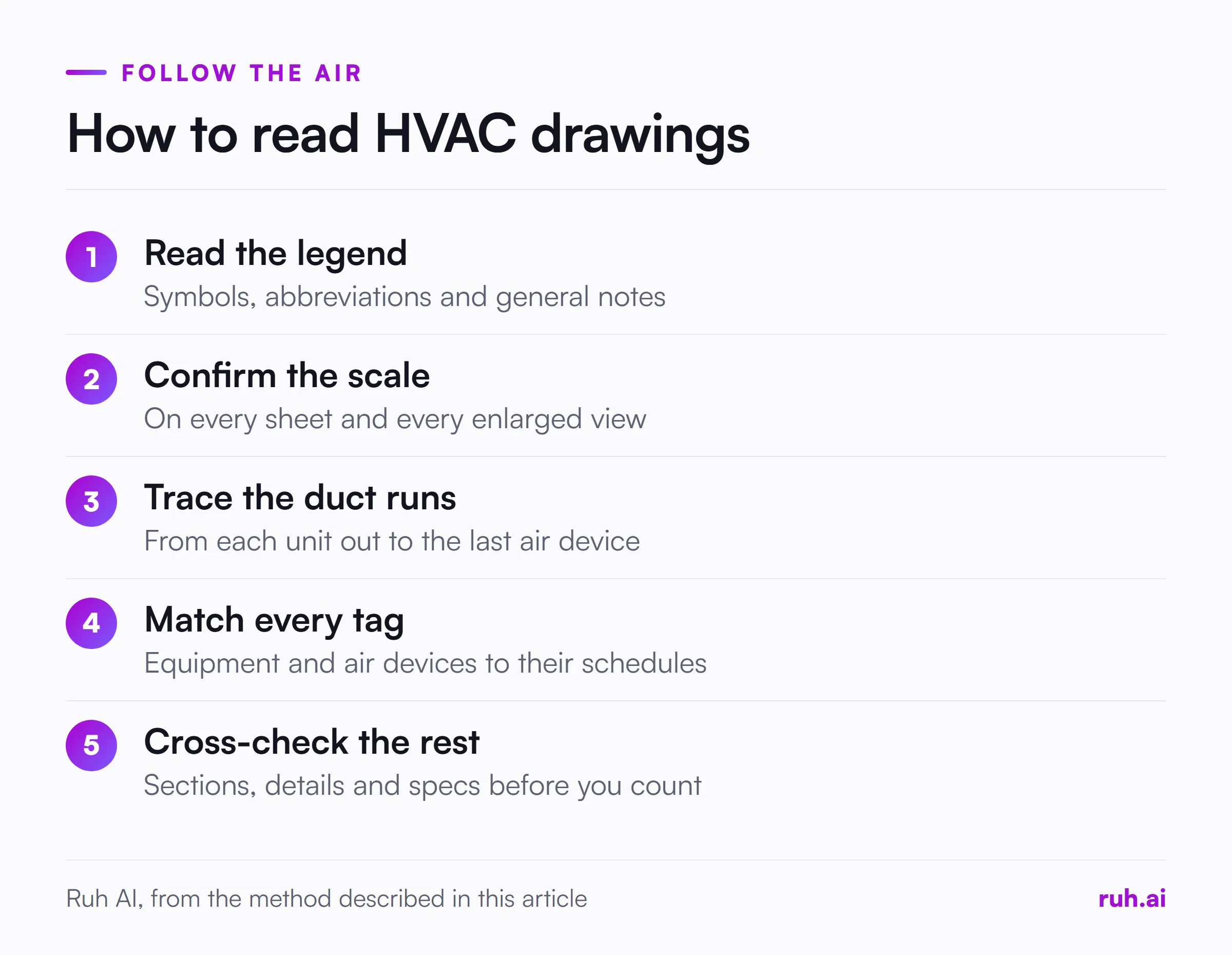
Q: How do you read HVAC drawings? A: Read the legend and general notes first, confirm the scale on every sheet, trace each duct system from its unit to the last air device, match every equipment and air device tag to its schedule, then check sections, details and specs.
Q: How are duct sizes shown on HVAC drawings? A: Rectangular duct is labelled width by depth, such as 24x12, and round duct by diameter. The legend says which dimension is the side shown in plan. The size changes after branches, so read it after every transition.
Q: What is an HVAC equipment schedule? A: It is a table on the mechanical schedules sheet listing every piece of equipment by tag, with its capacity, electrical data, weight, accessories and remarks. Each tag on the plans points to one row.
Q: What do SA, RA and EA mean on mechanical drawings? A: On most sets, SA is supply air, RA is return air, EA is exhaust air and OA is outside air. Check the legend, because abbreviations vary between designers.
Q: Why do fire dampers get missed in HVAC takeoffs? A: Fire dampers go where ducts pass through rated walls and floors, which are shown on the architectural life safety plans. If the mechanical plan doesn't draw every one, a takeoff from the mechanical sheets alone misses them.
See how Ruh prices your takeoff from your own rate book on the construction estimating software page.